


JoePaddie
-
Posts
8 -
Joined
-
Last visited
Content Type
Profiles
Forums
Gallery
Events
Posts posted by JoePaddie
-
-
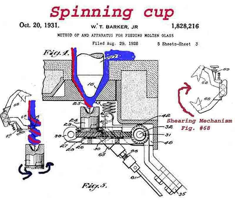
For the following, please reference Fig 4 of the patent drawing above.
I've come to the conclusion that whoever did the annotated drawing of blue and red molten glass and superimposed it on the patent apparatus drawing above, helped to create a huge confusion factor with respect to how the spinner cup actually functioned. It appears that this drawing has been floating around these forums for some time.
If you look at reference #25 in the center of the cup in Fig 4, you can see the "rod" that is claimed to have existed. In fact, the original patent description refers to #25 as a "groove". And #24 in the above referenced drawing is the cup itself which the patent description states "may have grooves #25 provided in its inner surface".
The spinner cup (#24) as mounted on the machine above was originally drawn on the actual patent plate with a cutaway depiction of the internal "spherically" shaped cup with a "groove" cut in it. In the original patent drawing there is a horizontal line that is clearly drawn across the top of the cup. In Figure 4 above the line disappears and the "groove" magically turns into a "rod". Go figure.
When you think about it the inner stationary "rod" never made sense anyway ... unless it can be retracted down the center of the cup. But as noted, not all the cups had a center hole. And there is no way such a "rod" could be afixed (or retracted) from above. Otherwise the first time the pivot arm is cycled to tilt the cup 90 degrees and eject the cork, it would break the "rod" or jam.
-
2 hours ago, lstmmrbls said:
One of the most important parts was the metal rod the glass flowed down under the orifice. This gave the stream resistance allowing it to corkscrew.
Thanks. This is very interesting.
So the 1/8" hole down the center of the spinner cup contained the rod, right? Was the rod fixed or did it rotate with the spinner cup?
When the gear driven spinner mechanism is pivoted about the shaft (#32) to eject the marble, has the metal rod been retracted somehow?
-
Thanks Alan. Appears to be a hefty little guy. These parts must have gone through a number of design changes and iterations over the years.
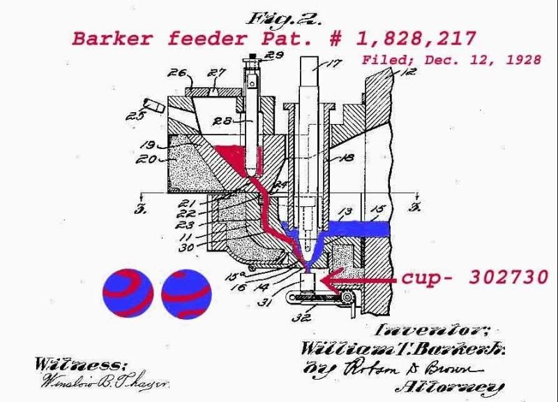
Looking at the 2nd patent drawing of 1931 above, what are your thoughts as to how these were mounted? I'm guessing they were pressed into the flanged holder (#24) and screwed down (#29) to the top of the helical spline gear (#27).
At first I wondered if the approximate 1/8" hole down the center of you spinner cup might be a centering hole. The "center hole" on Ron's spinner cup appears much larger though ... so then I was thinking it was meant to bleed off air that might get trapped beneath the molten glass ingot.
But then I saw part #25, which appears as though it might be an ejector assist pin. (Unfortunately, whoever used the highlighting to indicate the molten blue base and red cork material, has covered up the top of part #25. Although the blue and red spiral may functionally depict what will happen to the material, it does not happen outside of the spinner cup as shown).
Brain Storm Rules! Any and all ideas appreciated.
-
-
-
Hi All! I'm a newbie here and this topic fascinates me as well.
On 2/9/2021 at 8:57 AM, Steph said:Dani posted this page from Roger and Claudia Hardy's Akro guide. Has a lot of info in it, though it doesn't all make sense to me. (I'm getting hung up on the probably trivial point of it looking like the glass was dropped halfway down the rollers.)
I would add that the cup rotates to drop it in the funnel, before it is deposited onto the rollers.
EDIT: Ooops! I now see what you were talking about Steph, in regards to the location of the spinning cup mechanism and its location with respect to the rollers in Burnett's hand sketch above. I think it is meant only to be a "functional" drawing ... and as such he was taking artistic liberty. haha
On 2/9/2021 at 5:36 PM, wvrons said:Excavated Akro corkscrew spinner cup
This is a cool spinner cup! Did you dig it up yourself? What a piece of history. Wish I had one.
If you don't mind my asking: What is the approximate outside diameter at the top of the spinner cup? And what is the approximate inside diameter of the small hole at the bottom? And do you know why the smaller hole is there?
There are two patent plate drawings that I've seen in a past forum. I'll try to go grab them and provide links.

Akro Spinner Cup?
in General Marble & Glass Chat
Posted
Me neither. The two drawings included here, clearly show the modification that was made to the original patent drawing to fit the false theory of a "rod". (The horizontal line across the top of the spinner cup has been erased in the the modified drawing).
As noted in my previous post above, the patent description refers to #25 as a "groove" NOT a "rod". The patent drawing was intended to provide a cross sectional view of the internal cup with a "groove" on the back wall.